Note: Click on any photo to enlarge it!
| I started out with the 6 RPM 12V DC Gearmotor from All Electronics. I slid off the black protective cover, to expose the motor contacts (much easier to work with than the extra wire). | 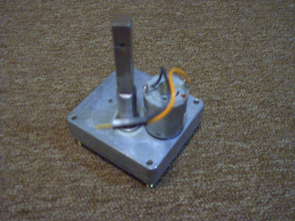 |
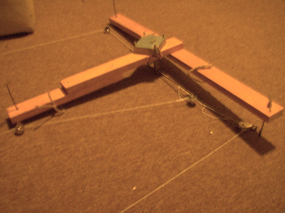
| Since the FCG is basically a three-point marionette, I decided to construct a T-frame out of wood, with the top of T 30" long and the height of the T 20" long. (The crank, built of 3/16" thick coat hanger wire, is also shown here.) |  |
| I chose to build the T in two layers for several reasons: First, overlapping adds strength, and second, the extra thickness compensates for the unneeded length of the motor shaft. All measurements necessary to build the T are on this image. | 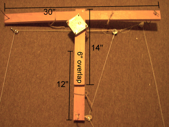 |
| To accommodate the motor, I drilled a 1/2" hole (for the shaft) and then a 1" hole (for the motor) in the piece that makes up the top layer of the T. I used a Dremel tool to enlarge the 1" hole untile the motor fit snugly, and then I bored out the space between them as well as the edge of the 1" hole on the top side (see picture) so the motor could slide all the way on. | 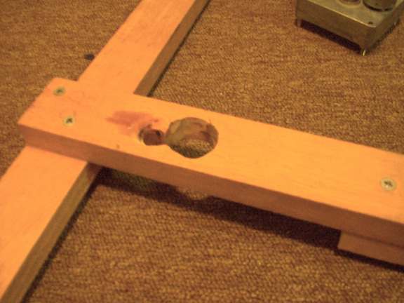 |
| This picture shows the T bottom up, with the motor in position. The shaft is about 2" from the top of the T, but the exact position is unimportant. As this picture also shows, I drilled a 3/16" hole in the motor's shaft while it was in a workbench-mounted vise (not shown). | 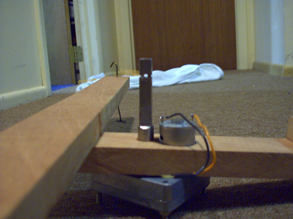 |
| Next, I bent a 16" long piece of 3/16" (very strong) wire coat hanger into an L shape 2" from the end. I slid the long end through the hole in the motor shaft, and did not secure it until I knew how much motion I wanted to generate. I placed the bushing on the short end and made another bend to secure it. | 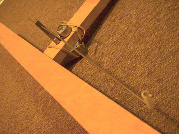 |
| In case you were wondering what the bushing is for, its purpose is to make this wahser spin freely. This prevents the 3 strings that are tied to the holes drilled in the washer from tangling or twisting as the crank revolves. The washer should fit snugly on the bushing, so it doesn't fall off. | 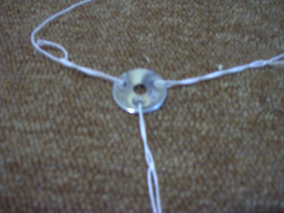 |
| I suspended a pulley from each end of the T frame by drilling a hole through the wood about 1 inch from each end and dropping T shapes from 8" coat hanger segments through, then bending them into hooks for the pulleys. | 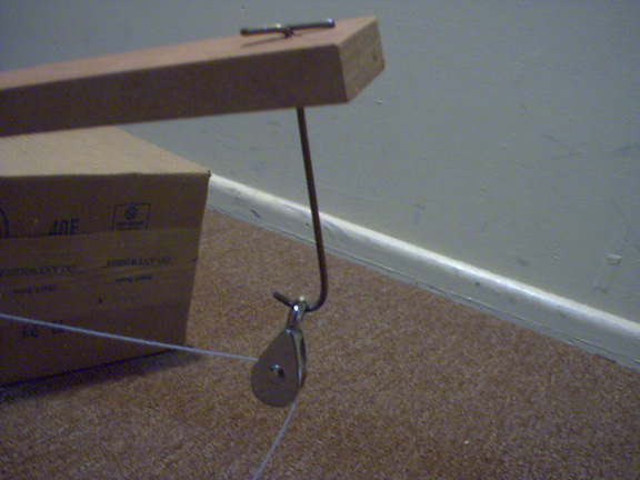 |
| Now, the 3 strings each went from the horizontally revolving (but not rotating) washer at the end of the crank, to pulleys that each converted the crank's motion to non-synchronized vertical bobbing movement. At this point, I was basically done, and basically happy with the chassis. | |
| I decided to test the chassis by mounting it to the fortunately exposed ceiling structure of the workroom. Before I did this, I temporarily removed the crank from the motor and secured the motor with 2 rubber bands stretched from the screw on 1 corner of the motor, under the chassis, and back up to the opposite corner. The bands can be seen in this picture, as can the loops of twine that suspend the T frame from 2 nails and a hook in the ceiling, and the alligator clips and coord from a 12V AC adapter that I had lying around and used to power the motor. The blue pole on the left is a blacklight that I stuck in a mass of rope hanging from the ceiling and used to test my puppet as I built it. To test the chassis, I plugged in the AC adapter, hooked up the alligator clips to the motor leads, and watched my weighted strings bob up and down...all for under 20 dollars! |
 |
| This concludes the Chassis section. If you have any questions, comments, thoughts, information, inspiration, or plain old desire to contact me, feel free to email me at mooseboy@optonline.net. [Back to Top] |
|